


Evaporative tower PMS 200/300/600CV
The model of the PMS/PMD series proposed to you (for waters of normal chemical-physical composition and clean, with a temperature not exceeding 55°C), consists of:
- ENCLOSURE (body, cap, and optional tank) entirely made of fiberglass reinforced polyester resin, structurally self-supporting and of exclusive design, with an external finish with UV protective gelcoat.
- SPLASH GUARD FINS made of fiberglass reinforced polyester resin (only on the version with tank).
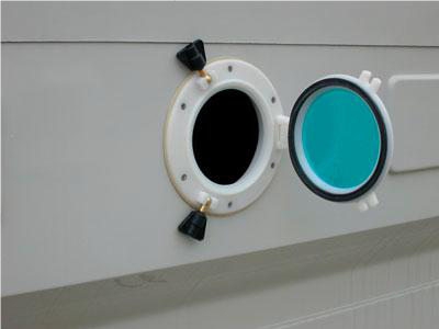
- CIRCULAR INSPECTION HATCHES with a polyamide body and polycarbonate window, easily openable for convenient inspection inside the tower.
- FILL PACK (or heat exchange pack) type k19, composed of panels made of self-extinguishing and rot-proof PVC sheets, thermoformed under vacuum and subsequently glued together. The fill pack thus produced has a shape, composition, and dimensions optimized for air/water contact inside the tower and the subsequent heat exchange process.
- DROPLET SEPARATOR composed of panels made of self-extinguishing and rot-proof PVC sheets, thermoformed under vacuum and subsequently glued together. The shape and dimensions of the panels are designed to minimize the entrainment of water droplets by the air stream drawn by the fan.
- SUPPORTS for the fill pack and droplet separator (if provided) in hot-dip galvanized steel.
- WATER DISTRIBUTION SYSTEM made with PN 10 PVC unified pipes and fittings, consisting of a main collector and one or more threaded fittings to which the spray nozzles are fixed. The system is designed to ensure a uniform and homogeneous distribution of water to be cooled over the fill pack.
- SPRAY NOZZLES made of isotactic polypropylene, static type, with large passages and self-cleaning. With exclusive design, the 120° spraying angle and the full cone ensure perfect wetting of the fill pack.
- PRESSURE GAUGE ASSEMBLY composed of a three-way fitting, glycerin-filled pressure gauge with AISI 304 body for measuring the inlet water pressure in the tower, drain valve for water hardness control.
- HYDRAULIC CONNECTIONS threaded for cooled water intake, overflow, float replenishment, and bottom discharge, located in the water collection tank (if provided).
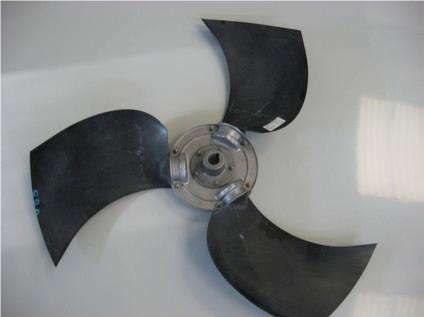
- AXIAL VENTILATION SYSTEM with direct coupling.
